0176// General Steps to Measure Positional Controlled Pins by CMM
- Oct 13, 2018
- 2 min read
Due to high demand from the audience for GD&T practical calculation, we will have a simple sharing how to use a touch trigger probe CMM to measure some of the positional controlled pins such as locating pins or dowel pins.
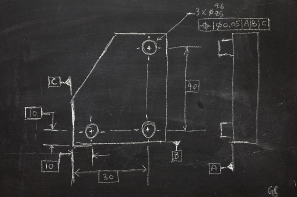
Let said we have a drawing as shown below:

Then, your supervisor asked you to measure its pin's true location (position control). Below will shows you the steps by steps how you going to measure it. First steps, on your laptop and read this blog...
Step 1: Workpiece Fixturing
This is the most important step because fail to fixturing your workpiece will result in inaccurate measurements.
By applying 3-2-1 rules, we know that we need three surfaces contact with 3 points, 2 points and 1 points for each of the surfaces. So, we need a flat surface (approximately equivalent to 3 points) on CMM, two bolts and one bolt as shown in diagram below. For my personal preference, I prefer to put all my support on datum surfaces. However, if you noticed, datum A is at the root of the pins. Therefore, I using its far side surface for my three points support.

Tips: always remember to check whether your fixtures will hindrance your styli moving paths.
Step 2: Datum Establishment

Measure plane 1 with point A1, A2 and A3
Align baseplane (x-y plane) and create origin (Z=0) for plane 1
Set clearance height ("clearance height " this term may vary for different CMM)
Measure two points, B1 and B2. In this step we need to ensure you measure B1 before B2 because this will determine direction x axis.
Measure line 1 by connecting B1 and B2
Align this line as x axis
Measure two points C1 and C2.
Measure line 2 by connecting C1 and C2.
Measure point 1 by intersecting line 1 and line 2.
Set this point as (x,y) = (0,0)
Check the origin and direction of the axis by moving your stylus around.
Position Measurements

Doing some simple math here. Based on basic dimension, calculate all true position coordinates. Remember use the PCS (part coordinates system) not the MCS (machine coordinates system)
Measure circumscribed circle for true position 1 (use circumscribed/ inscribed/ Gaussian are based on its functional requirements, details for this will discuss in future posts)

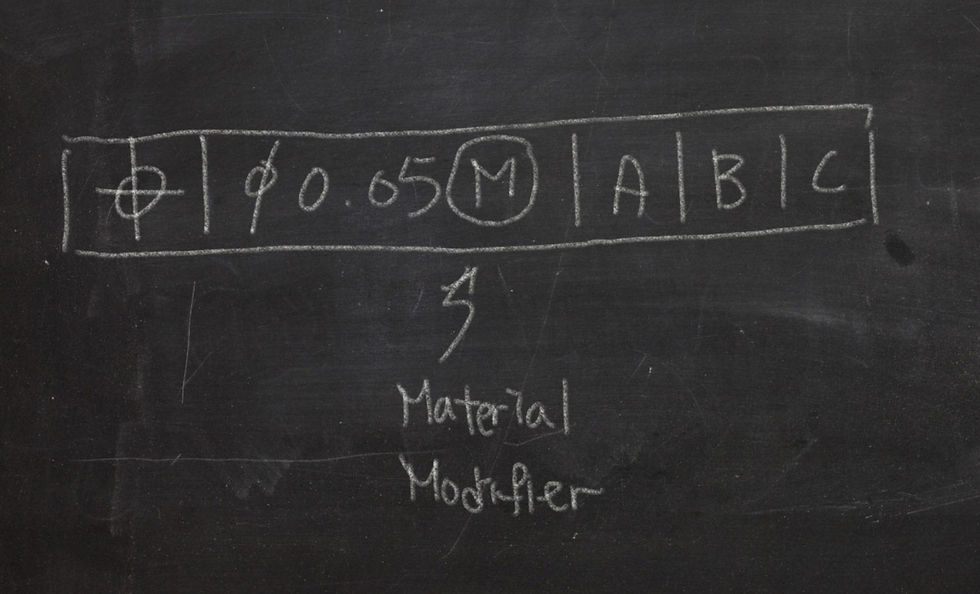
If your tolerance zone size come with material modifier (in this case, MMC, maximum material condition). Then, you need to doing an extra step here. Depending your machine, this step may vary. In this post, I will use Mitutoyo CMM system as example. In the window which you use to measure circles, you need to set "Further tolerances options ". In the window it pop out, set "Datum Label" as "MMC1"
Measure position. Set "Diameter symbol"(if your tolerance zone shape is cylindrical), "MMC" (if your tolerance zone size applies to MMC), x=10, y=10
Now you have positional measurements for true position 1
Then, you can repeat step 1 to 5 for true position 2 and 3 with its respective coordinates
Author: WONG GUAN BOON
Publish date: 11 Oct 2018
Return 0;


Comments